
| Home | Products | Services | Projects | Contact Us |
|
I recently bought a UT61E multimeter which I think is a great multimeter for the price.
However I was initially disappointed that it did not have an auto power off feature.
I have come up with a relatively simple modification to the UT61E which enables the auto power off. Another small
modification to the RS232 interface board automagically disables the auto power off when connected to the P.C. Details: Firstly I checked out the the circuit diagram for the UT61E (Thanks to the EEV blog forum member sdttn UNI-T UT61E Multimeter teardown Reply #114) and the datasheet for the ES515922 which is the main controller IC for the UT61E. I found that the ES515922 does support the auto power off feature. However when the RS232 data out function is enabled on the ES515922 by connecting the RS232 pin (pin 111) to V- the auto power off function is disabled. On the UT61E the RS232 output is permanently enabled with a PCB connection from pin111 to V-. UT61E Multimeter modifications: To confirm the auto power off feature worked I firstly cut the PCB track which connects pin111 of the ES515922 to V-. Sure enough after about 15 minutes the meter automatically turns off. The meter warns you that it is about to shut down with 2 short beeps every 5 seconds for about 15sec. According to the ES51922 datasheet the auto power off time can be changed to 30min if you prefer by connecting the APOSEL (pin 112) to V- but I haven't tried this. Obviously the problem with just cutting the connection between the RS232 enable pin and V- is the RS232 output is disabled. Fortunately the UT61E optical isolation port for the PC interface has a clear window for 2, 3mm LEDs and only the transmit LED is fitted. I added an 3mm NPN IR phototransistor to the spare optical port with the collector connected to the RS232 enable pin (pin 111) and emitter connected to V-. |
|||||
 |
|||||
|
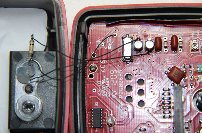
Above is an image showing the spare 3mm optical port on the UT61E fitted with the IR phototransistor. It is held in place with a small dob
of hot melt glue. I also added a 100k pullup resistor from the collector of the phototransistor to V+ which can be soldered to the positive
side of C33. I connected the emitter of the phototransistor to VB- by soldering a wire to the negative side of C31. |
|||||
 |
|||||
|
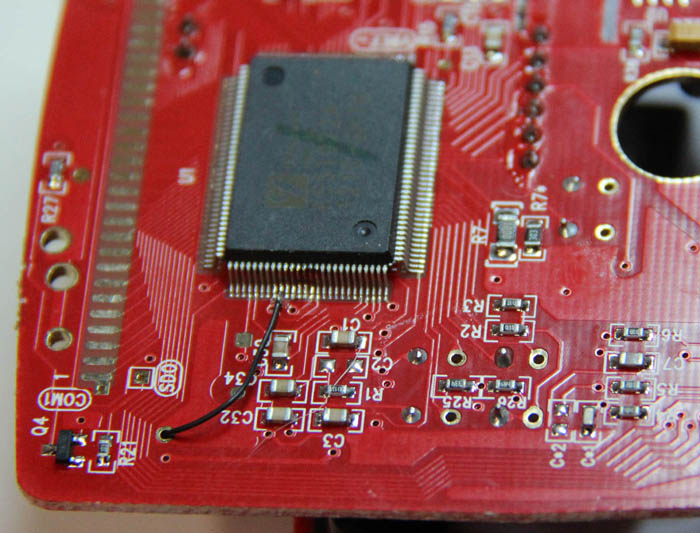
Above is an image showing the connection to the RS232 enable pin (pin 111) of the the ES51922.
The wire feeds up through a hole in the PCB and connects to the collector of the IR phototransistor. The cut track is just below the wire
link so you can't really see it in this photo. |
|||||
 |
|||||
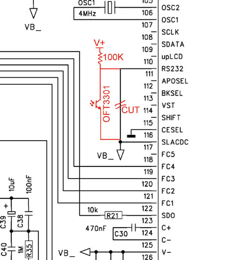
| Above is the schematic diagram of the modified section of the UT61E. The mods are in red. | |||||
|
I used a OFT-3301 IR phototransistor because thats what I had available, most any IR phototransistor in a 3mm package should do the trick. That's
it for the modifications to the multimeter. I insulated the mods with some heatshrink tube so nothing could short out and screwed the multimeter back together.
We now need to modify the RS232 optical interface board so that when it is connected to the UT61E the auto power off is disabled and the RS232 output is enabled. RS232 Interface Board modifications: The RS232 interface board also has a spare window position for a TX LED from the PC. The interface PCB even has a position for the 3mm TX LED connected between V+ and TXD from the PC which is not fitted. I fitted a 3mm IR LED and a 10K current limiting resistor to the interface board. The TXD line from the PC idles low so the IR LED is permanently on when connected to the PC. I used a SFH4350 IR LED, again because thats what I had available, most any 3mm IR LED should do. The 10K current limiting resistor limits the LED current to around 1mA so it shouldn't place too much load on the RS232 port pins.
|
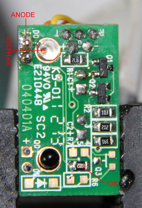
Above is a photo of the RS232 interface board with the IR LED and current limiting resistor fitted.
|
|
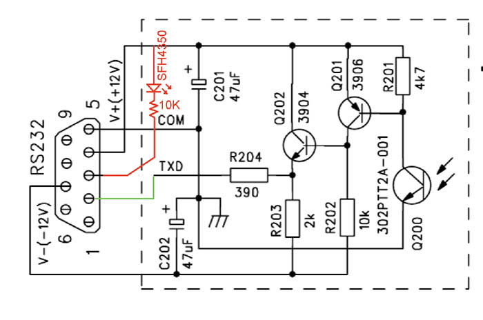
Above is the schematic diagram of the modified RS232 interface board. The mods are in red.
|
Note: The original circuit diagram for the RS232 interface board showed the TXD from the multimeter going to pin 3
of the DB9 connector, but the PCB was wired to PIN2 of the DB9 connected. The PCB is correct for DCE equipment so the original
schematic has an error. I have corrected the error on the modified circuit above with the green trace. |
So now, when the interface board is slid into the optical port of the UT61E the IR photo transistor added to the UT61E turns on and connects the RS232 enable pin to V-. This enables the RS232 output and disables the auto power off mode of the meter. The PC icon in the bottom left hand corner should turn on when the RS232 optical port is connected to the UT61E with the interface software connevted. The UT61E interface software should be running for everything to work because the RS232 handshaking lines must be in the correct state to power up the RS232 interface board. Disclaimer: All care but no responsibility has been taken in presenting this information. You will most likely void any warranty for the equipment should you perform this mod. I'm happy to answer any questions you may have when I have the time. A forum thread discussing this modification can be found here on EEVblog. |